I did this post last week where I tested the claim of up to 9x faster tab switching with AutoCAD 2024. My thought is this would be great for my Civil 3d users who use a lot of tabs. Faster is always better, right?
Unfortunately this speed increase did not transfer from AutoCAD 2024 to Civil 3d 2024. I suspect this has to do with the fact that Civil 3d regenerates object very differently than straight AutoCAD.
The good news is Civil 3d 2024 managed to do this about 11% faster over 5 trials with Civil 3d 2024 always coming out faster than the 2022 version.
I also tested to see if this speed increase in tab switching also applies to publishing the same 50 sheet drawing set. Unfortunately, the answer is no to that (even in AutoCAD). I suspect whatever change was made to speed up tab switching was not applied to the publishing code.
I had a drawing with over 50 layout tabs so I bashed together this code to switch between 50 layout tabs and time the results. This code is specific for these drawings. You can see the code at the bottom of this post.
Here we are testing performance between 2022 (left) and 2024 (right).
Video has no sound.
My experiments found it being significantly faster at about 4-5x faster. I wasn’t seeing 9x speed improvement, and would be curious what changes could be made to achieve that.
Code below. This is relying on knowing the names of the layout tabs.
I often see users new to grading with Civil 3d make the same errors reviewing surfaces. Here we are going to continue our series and show you a few shortcuts to help you review surfaces faster.
I see this often with new users, they want to check the grades, and do it by copying a grade label all over the place. To review these they need to review each number. Lets supercharge this and talk about surface analysis!
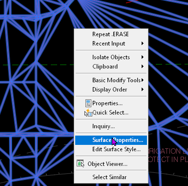
Select the surface, right click and select Surface Properties.
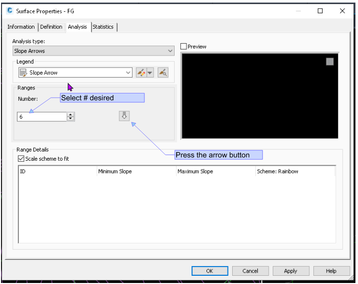
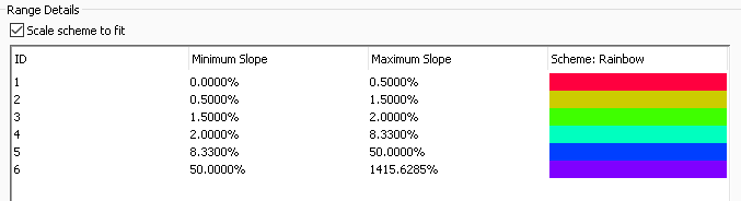
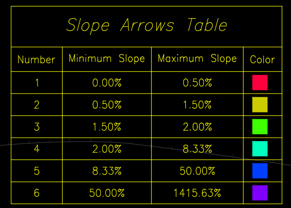
Setup the desired # of surface analysis. I usually use this scheme:
I usually do this for the following reasons. I want to flag any slope under 0.50% as too flat to drain. Often I may want to increase this range. 0.50-1.50% I also want to check out. 1.5%-2% is flagged so we can check for any issues with ADA cross-slope. 2-8.33% is acceptable for ADA longitudinally. 50%+ I want to check for any too-steep slopes.
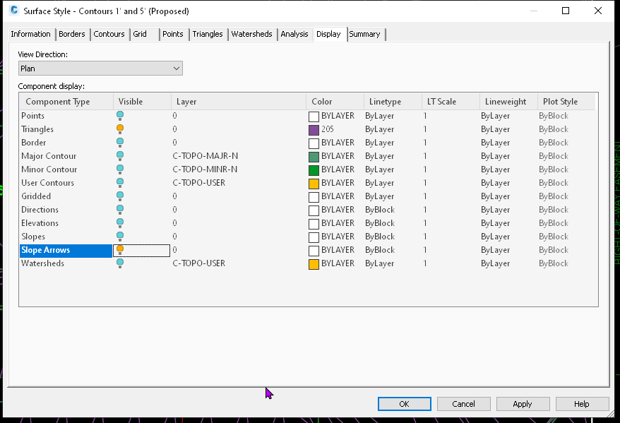
To get these to display, edit your surface style and make sure Slope Arrows is on (visible).
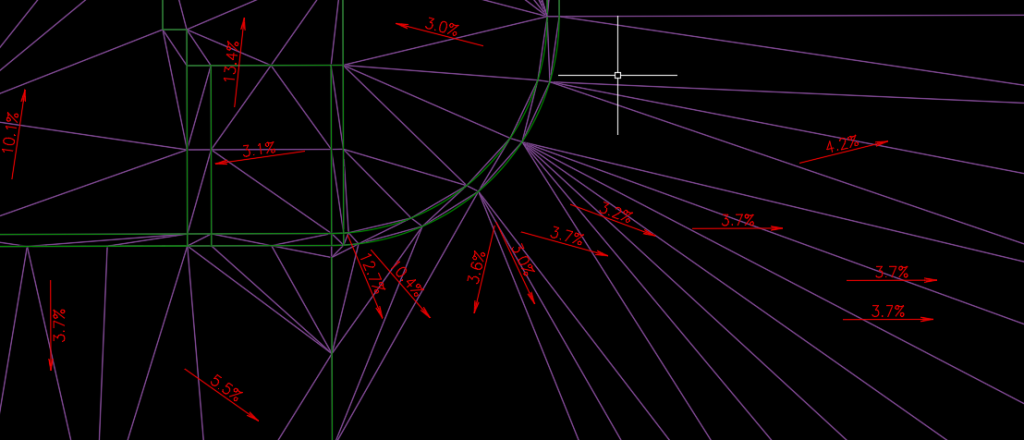
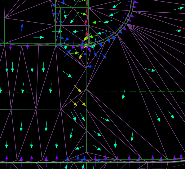
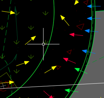
Now I can review my surface slopes by looking at the surface.
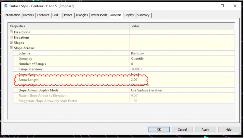
One issue you can have is the slope arrows are too/big or small.
You can change the size of the slope arrow by editing the style.
Adjust the slope arrow length as needed.
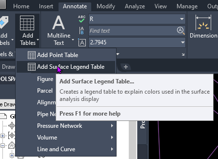
If you are printing this for review by your team, you can add a surface legend table
After selecting ‘Add Surface Legend Table’ and selecting your surface, it will ask what type of table you need. Select A for Slope Arrows. It will ask if you want a dynamic or static table.
Tin Lines Make Sense out of Chaos.
When reviewing the slope arrows, sometimes making sense out of them can be difficult. Turning on the tin lines helps make sense out of chaos.
This will conclude part 2 of this series. I will post part 3 sometime after Autodesk University in New Orleans. Hope to see you there.
Labels lie all the time in Civil 3d. You need to be aware of HOW they lie when you review drawings
I find a lot of new Civil 3d users do a good job of understanding the Surface Creation tools. The available tools to review surfaces and the problems that can result are less understood.
In this series, I am going to go through the tips I have for reviewing surfaces. There will be some good tips both for the newer Civil 3d user and tips experienced users can use to review drawings. Most of the issues in these posts come from actual drawings, not ones I have created to demonstrate these issues.
Tip #1, increase contour interval. Increasing the contour interval can quickly reveal issues with the surface. In the example image below left, that contour looks a bit funky. Once I increase the contour interval the issue is quickly revealed.
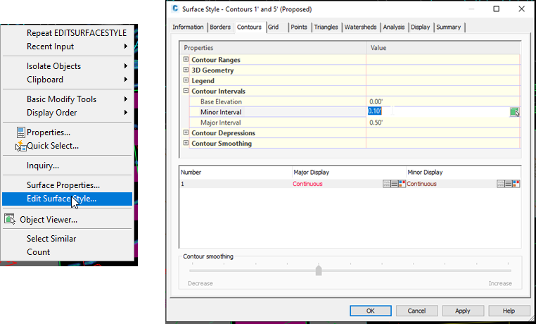
To increase the contour interval, Select the surface, right click and select ‘Edit Surface Style’. Go to the surface style, contour tab and increase 10x.
Here is a similar issue that is revealed with this change.
How Labels Lie
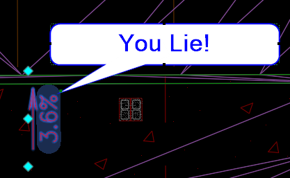
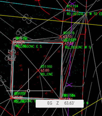
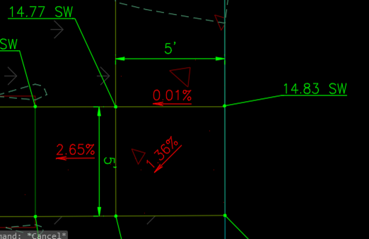
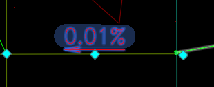
Labels lie all the time in Civil 3d. You need to be aware of HOW they lie when you review drawings. Lets take a look at this example below. Can you see the issue with the slope label below?
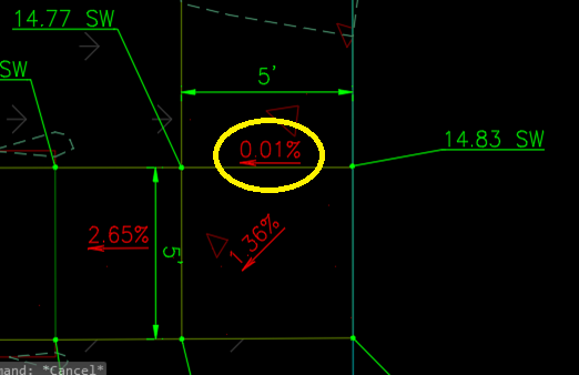
Circling it as below probably helped you find it, right?
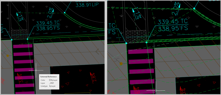
Reviewing the spot elevations, clearly this isn’t 0.01%. Lets select the label…
We can see here that the grips are going past the breakline. You need to make sure that the grips for two-point labels aren’t crossing breaklines. In this case the slope to the left of the breakline is different than the slope on the right. So it averages these out. Its not good!
Two suggestions here:
First its a good idea not to make your two point grade labels any longer than they need to be. This will help you eliminate the issue like above, cause things are going to move.
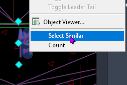
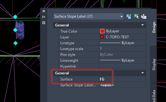
Second, before putting your plan into any sort of final state, double check ALL the labels are referring to the correct surface. Select a single label, and then select similar.
Now that I have selected a single label, and select all. I want to verify that all my labels are referencing the correct surface.
That concludes Part 1 of this series. I will post part 2 in a few days. If you have a suggestion, please leave it below in the comments! Thanks!
Google street view is a very powerful resource for engineers. Often times it takes some fiddling to find the exact point you want in street view.
I wrote some code to help with the process. What this code does is take the Northing and Easting in your Civil 3d drawing and convert it to Lattitude & Longitude. In order for it to do this you have to have a coordinate zone assigned to your drawing in the Civil 3d Units & Zone Tab. I demonstrate this in the video, but you can also access it by typing in EDITDRAWINGSETTINGS.
Check out the video below, and the code at the bottom of the page. Thanks!
; Written by Brian Strandberg, c3dk.com
; email: hello@c3dk.com
; Transforms coordinates from the X & Y in your drawing
; to Lattitude & Longitude
; then opens google street view at that point.
; code is not fully debugged
; requires a coordinate zone is assigned to your drawing.

(defun c:gsv (/)
(command "UCS" "World")
(if (not (getvar "CGOECS"))()(alert "fail - set coordinate zone first"))
(setq pkpt (getpoint "Select Point to see in Street View"))
(ade_projsetsrc (getvar "CGEOCS"))
(ade_projsetdest "LL84")
(setq cvp (list (car pkpt) (cadr pkpt)))
(setq result (ade_projptforward CVP))
(if (null result)
(alert "\nError in Transformation "))

(setq gsv (strcat "http://maps.google.com/maps?q=&layer=c&cbll=" (rtos (cadr result) 2 8) "," (rtos (car result) 2 8)))

(command "UCS" "P")
(command "browser" gsv)


); close defun
Translating your drawing from one CAD Standard to another – fast.
Data management is huge deal when working with AutoCAD and Civil 3d. In this case, I am working on translating our Survey Team’s CAD Layers to a large City’s CAD Layers. We want this to run as a script so it is very easy for our team members to run the process.
I start this process with a planning step first. This sounds pretty boring, but it is essential work. I want to know exactly what needs to be done before I start doing it. Then I will encode this into a script and the LAYTRANS command.
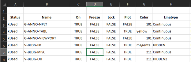
Step 1) I start a new drawing with our survey template, and type in LAYER. Select a layer from the list, then key in CTRL + A. Now that all layers are selected, press CTRL + C to copy the layers.
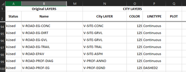
Step 2) Start a new excel file and paste the layers you previously copied. Now you have a nice listing of all your layers. Now it’s time to go line-by-line and determine what each layer needs to be translated to. You may find you just want to delete some layers.
Step 3) Now that I know I’m going to do with each layer, I need to start working in CAD to achieve the desired effect. We will be doing this with many drawings over time, so I want the result to be scripted as much as possible. That way the survey team can just run the script and check the output.
I have identified a large number of layers which won’t have anything on them for this type of survey. They are usually used for staking drawings. I will remove these layers. I’m also going to purge unused blocks.
Here I have started writing my script. I usually write these as a series of lisp statements. In this case below, I am purging blocks and then deleting a layer from our template that will not be used in this type of survey.
Now its time to setup the translation matrix with the LAYTRANS command. This is straightforward, you go through each layer on the left (current drawing), vs the panel on the right which is the one you are translating to.
You can see in the bottom pane what the translation will do. Old Layer Name – New Layer Name and what that layer will look like. Don’t forget to save while configuring this! If you accidently exit, ya gotta start over. So, you need to plan so you can do this in one shot.
Make time to check out the settings. If you look at the first 4 shown below, its giving you the option to do a SETBYLAYER command right in the layer translator. A nice feature!
Now that we have created and saved our translation matrix, its time to add two more lines to our script.
What is (acet-laytrans) ? This is a lisp statement to run your translation. You can of course, bring up your translation normally with the LAYTRANS command, but this allows us to script the whole process. Sweet and fast. We must precede this with the statement (arxload “Laytrans”) to ensure the laytrans functions are loaded in CAD.
We embedded a link to this script in our menu system. Check out the results below.